
在Hauhinco传统与创新是互不分离的。Hauhinco是1908年在德国斯普罗克霍威尔,鲁尔矿业的摇篮成立的。至今,Hauhinco仍旧牢记自己的由来。再过去的100余年间,公司经历了很多组织结构和市场环境的变化,并仍旧不断地推陈出新,为市场带来创新性的产品。这些经验使得Hauhinco在市场中独树一帜。
Hauhinco是一家拥有悠久历史的成功的中型公司。如今,Hauhinco是世界领先的水液压应用领域供应商。我们的高压柱塞泵,阀以及系统被广泛地应用于世界各地的井下煤矿以及工业领域。而我们的员工正是我们成功的关键。
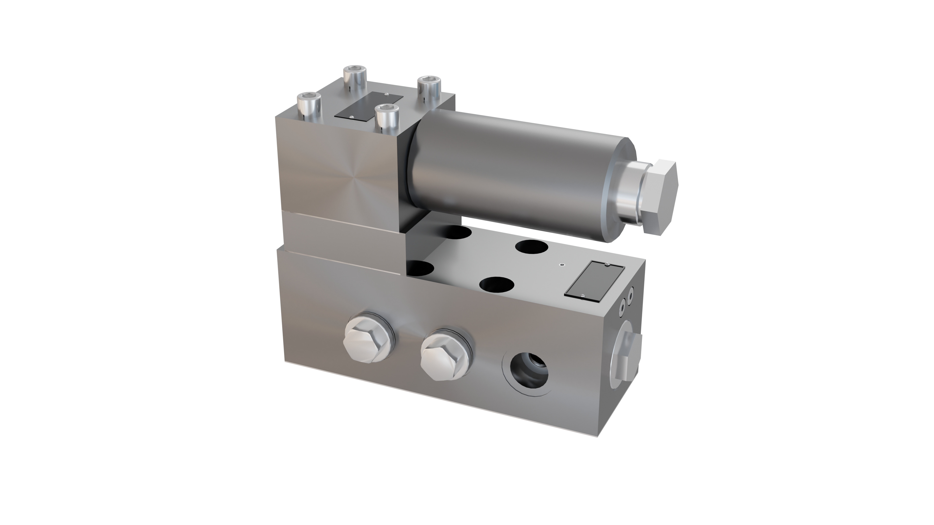
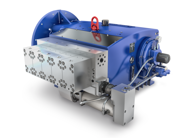
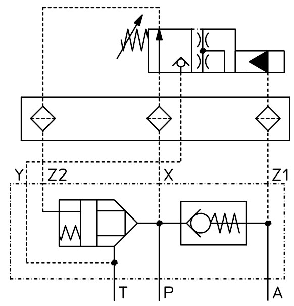
The pump bypass valve, the control pcb and the pilot valve form a valve unit controlling a pump in a pressure supply system with a pressure accumulator. Depending on the system pressure, the valve controls the working cycle of the pump, „load accumulator“ or „depressurised bypass“. The P-connector is connected to the pressure port of the pump, the A-connector to the pressure line of the system and the T-connector to the pressure-free tank.
The flow of the pump enters the pump bypass valve at the P-connector. In the basic position, the pressure generated by the pump is used to close the 2/2-way valve (2) via the X- and the Z2-line. This has the effect that the non-return valve (1) opens, and the pump flow is supplied to the system via the A – connector.
At the pilot valve, the required pressure value „PE“ is set by means of the adjusting screw (3). Depending on the setting value, the springs (4) generate a force pressing the valve piston (6) into the valve seat (7). Thus, the Y-line is shut-off from the X- and Z2-line, and the generated pump pressure closes the 2/2-way valve. The pilot valve changes over, when the hydraulic power resulting from the pressure exceeds the power set at the springs (4) at the A- and thus at the Z1-connector. Then, the piston valve (5) lifts the valve piston (6) off the valve seat (7). Thus, the control surface of the 2/2-way valves (2) is depressurised, it opens and connects the lines „P, T“ with each other. Thus, the pump flow is carried pressureless to the tank. Simultaneously, the non-return valve (1) closes and shuts off the backflow from the system. The valve piston (6) remains in the open position until the system pressure at the A-connector falls short of the set pressure value „PE“ minus the value of the switching hysteresis; the 2/2-way valve (2) also remains open for this period.
General | |
| Weight | see Order information |
| Installation position | any |
| Ambient temperature | -10 to 50°C (hydraulic fl uids, heed standard requirements) |
| Material Valve parts Material Seals | Stainless steel, bronze NBR, PTFE, PUR |
Hydraulic | |
Pump bypass valve H30, H300 | |
| Hydraulic pressure connector P, A, M | ≤ 400 bar |
| Hydraulic pressure connector X, Z1, Z2 | ≤ 400 bar |
| Hydraulic pressure connector Y | ≤ 10 bar |
| Direction of flow | P->T, P->A |
Pilot valve V300 | |
| Hydraulic pressure connector X, Z1, Z2 | ≤ 400 bar |
| Hydraulic pressure connector Y | ≤ 10 bar |
| Pressure fluid - Medium - Temperature range - Medium - Quality - min. filter fineness connection P, A, T - min. filter fineness connection X, Z1, Z2 | Water, HFA 5 to 40°C see Hauhinco media requirement, water, HFA Filter fi neness 100μm Filter fi neness 25μm (control pcb with filter inserts) |
| Pressure fluid - Medium - Temperature range - Medium - Quality | Mineral oil HLP according to DIN51624-2 5 to 50°C Cleanliness class -/19/16 according to ISO 4406 |
| max. switching rate of the valve unit | 0,2 Hz |
| Note: The maximum decrease volume flow of the consumer and the size of the pressure accumulator control the switching rate of the pump circulation control system. | |
| Use of other pressure fluids on request. | |
Included in the scope of supply | |
| Mounting screws of the valves |
| Description | Nominal size | Weight | Max. pressure | Basic position | Voltage | Note | Article number |
|---|---|---|---|---|---|---|---|
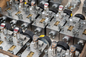
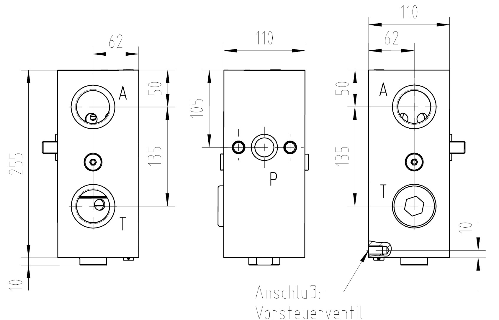
| Pump bypass valve H300 | DN25 | 20,0kg | 400 bar | 6264956 | |||
| Pump bypass valve H30 | DN30 | 20,0kg | 400 bar | 6264948 | |||
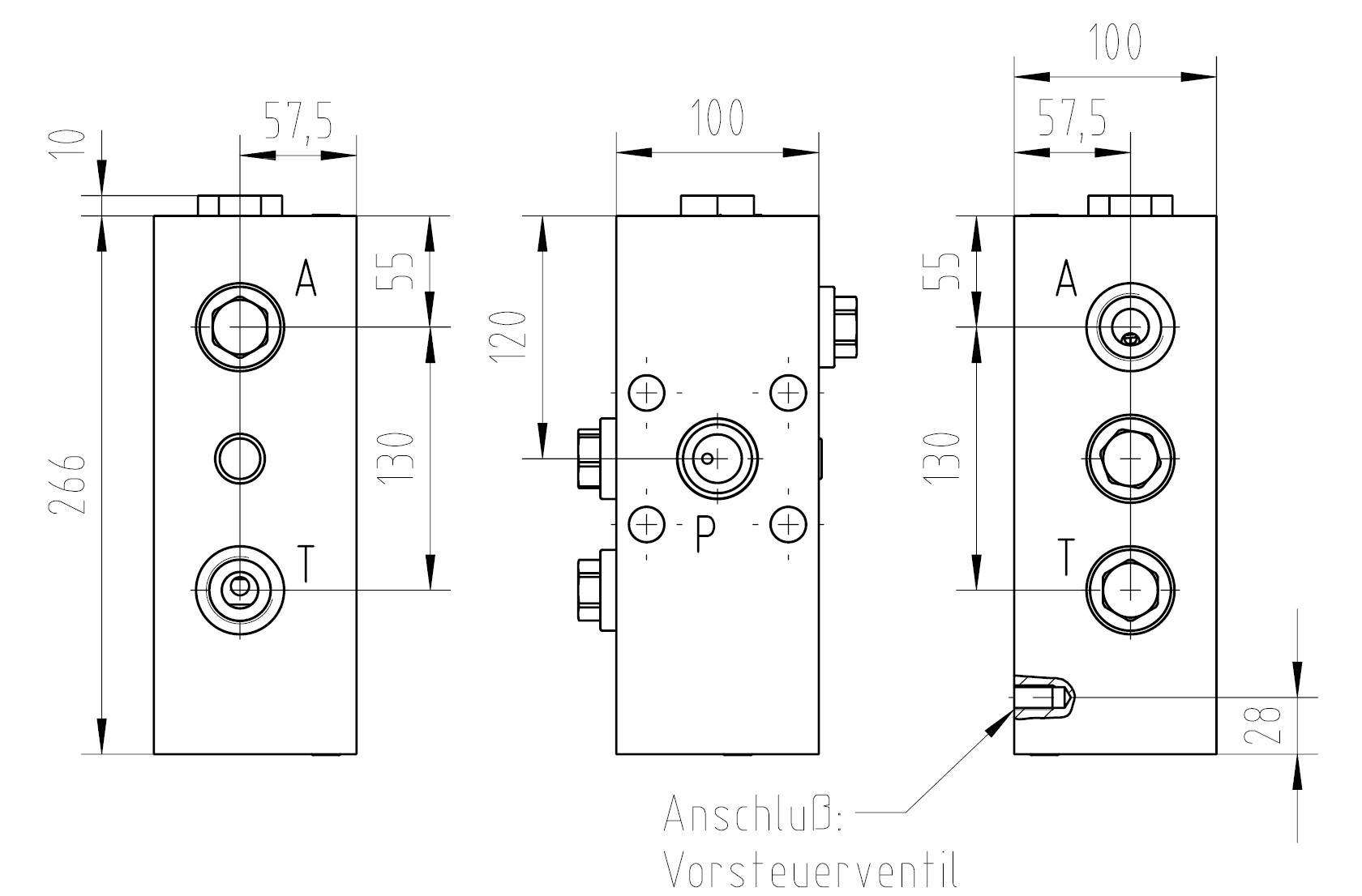
| Pilot valve V300/10 | DN | 10,0kg | 230-400bar (Einstellbereich) | Switching hysteresis 10% | 5100682 | ||
| Pilot valve V300/20 | DN | 10,0kg | 230-400bar (Einstellbereich) | Switching hysteresis 20% | 5100658 | ||
| Control pcb with filter | DN | 3,0kg | 6328423 |


